Engine wiring dgm
Engine Wiring Diagram
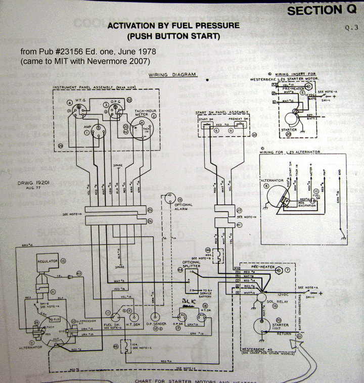
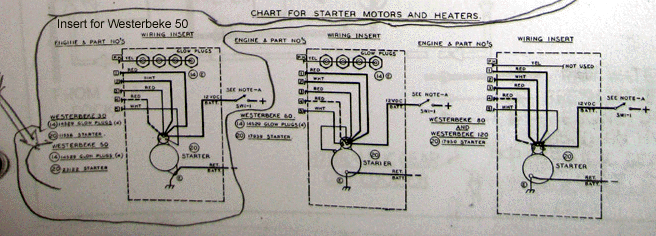
Note about the two pictures:
The two pictures above are parts of one 8x11 page of the Tech. Manual; the drawing was split only because -- since we captured the page with a camerea -- we can blow up each part of the content separately to try for a little more readable diagram. If someone later scans in this diagram in, there should probably be no reason to separate the parts.
Note about inserts:
The block in lower-right corner of big part of the diagram shows how one model's starter and pre-heating device(s) (if fitted) get wired in with the rest of the diagram. One of the other 4 wiring inserts shows the configuration for our W50 engine, and we've circled it and pointed it up to replace the "wired" one on the drawing.
The Alternator / Regulator stack on lower-left corner of larger picture shows what this editor thinks is the kind of alternator used on Nevermore.
We're guessing that the "Wiring for L25 Alternator" box drawn on the right side of diagram isn't applicable to Nevermore.

