Nevermore Systems Descriptions
This document purports to be an exhaustive list of Nevermore's various subsystems, expressed technically. Some sections document technical studies of some of the subsystems because we feel that other mariners will need the information sd they repair or enhance those subsystems. Other sections herein document findings from technical work we've done, which give other workers a chance to double-check their mates' understanding of the systems, in addition to learning more about Nevermore themselves.
It'll become apparent to the reader that the document will be incomplete in many areas, and possibly too detailed in others. Such readers are invited to become editors/researchers and fill in missing information and reorganize the info at hand.
Contents
[hide]BOAT SYSTEMS
standing and running rigging
standing rigging
running rigging
- MAINSAIL
- per lines drawing from web: P=41.5 ft (tack to head along mast), E=12.0 ft (tack to clew along boom)
- Dutchman furling system (Type A)
- traveller
- boomvang
- FORESAIL
- foretriangle: per lines drawing from web: I=47.0 ft (vertical along mast), J=15.0 ft (mast to tack point)
- Large genoa (what size?)
- Small genoa (what size?) (any head-/tack- pennants needed?)
- jib (what size?)
- furler (Seldén Furlex 200S) [see install/use manual & parts list manuals]
- operation:
- keep a little tension on furling line as sail is deployed, to keep line overwraps in furler drum
- keep a little tension on jibsheets while furling, to make a tight roll of sail on the forestay
- tension on furling line is considerable for first few turns of drum; however, NEVER apply too much tension if furler is "sticky"
- operation:
- halyard winch: dedicated, port side of mast;
- Operation:
- The Owner's Instructions page 6 directs that there be at least 2 turns of WIRE halyard, preferably 4, around the winch with foresails fully hoisted; and never should genoa halyard tension be taken on the rope halyard tail
- it follows from the above that we should not consider the deep grooving of the winch drum as being anomalous
- TODO: when we clean the winch, why not measure drum thickness to decide whether the grooving is excessive
- it also follows that the wire-to-rope splice will be wrapped on the drum (which ThomS learned is NOT desired usually)
- it further follows that (at least to Thom) it seems impossible to use the winch for spinnaker halyard because a rolling hitch around the wire genoa halyard will slip while we're offloading the genoa halyard?
- Operation:
- SPINNAKER
- asymetrical (with Raven!)
- pole (a huge pole is aboard, not being used)
deck hardware
- WINCHES (7 total)
| Winch # | Location | Lewmar Part # |
Features | Purpose |
|---|---|---|---|---|
| 1 | cockpit port | 48 ST | 2-speed self-tailing | foresail sheet |
| 2 | cockpit stbd | 48 ST | 2-speed self-tailing | foresail sheet |
| 3 | hatch port | 16 | 2-speed self-tailing* | mainsheet |
| 4 | hatch stbd | 8 | 1-speed self-tailing* | raise/trim centerboard |
| 5 | boom stbd | 8 | 1-speed | mainsail reefing |
| 6 | mast port | 30 | 2-speed | foresails halyards |
| 7 | mast stbd ) | 16 | 2-speed | main halyard |
- Via a rubber add-on
[see Sys_Descript_WINCHES for more info on winches.
Keel-Centerboard
The keel provides weight for righting moment, and also accommodates the slot for the centerboard.
Note that we were told that there is a "box" inside the slot that can be unbolted so we can lower the centerboard out. We didn't see such a thing Fall '07.
(See Owner's Instructions pages 4, 5, 5A for rigging and adjusting the centerboard pennant and tag line, and pages 14, 15, 15A for replacing the pennant.)
TODO: find weights of keel and centerboard. TODO: find out possibilities for removing CB.
QUESTION: is there excessive play in the centerboard? When hard on a tack with CB down, it vibrates. It sounds semi-horrid to ThomS, but others say "that's normal..."
Operation Hints:
- DO NOT let the pennant run free! I.e., don't let the centerboard drop!
- The instructions show how to place the block on the pennant so that the tag line will allow full upward position of the CB, and also allow full extension of the CB when the tag line is freed.
- Simplistic guidelines for positioning might (i.e. just dreaming some up Feb08) be:
- deploy down when on the wind
- pull up when running
- positioning too far up going to windward may give more lee helm (CR moves backwards), and of course allows more leeway
- positioning too far up going downwind may allow more yaw (or maybe not, if the sea's wavelength is just-so)
- the more up it's positioned, the less drag the CB gives
- what else?
Ship's Machinery
power train
engine
Identifying info from tag on engine:
- model: Westerbeke 50
- ser #: 18P/830A/0247B911
- spec : 18360 2.1
- date : November 1979 manufacture decoded from "0247B911" of serial number
(block #0247 per Svc Bul #132, or of engine per #242; date from "B911" )
REFERENCES:
- Our catalog of engine hardcover and web-based documents, including entries defining
- Tech Manual (ENG_TM), and references to subsidiary tech info on this wiki and on the web
- Westerbeke's Parts List (ENG_PL)
- a link to the Parts List put on the web by an independent parts supplier
- Tartan's Engine schematic dgm of 12-V DC circuitry which comes with the Engine
- a Wiring Diagram of the circuitry on this schematic is in section Q of the Tech Manual
'Misc observations' (useful in troubleshooting):
- Engine instrument panel gauges (05Sep07):
- Water Temp gauge
- * goes off left (cool) end with sender disconnected (good)
- * sender shows 360 ohm @ 100 deg, 25 ohm @ 230 deg
- Oil Pressure gauge
- * goes off left (0 psi) end with sender disconnected (good)
- (but note: Calder p.288 says most O.P. gauges go to high reading)
- * sender shows 460 ohm @ 0 psi, 44 ohm @ 50 psi, 0 ohm @ 80 psi
- Water Temp gauge
- See Tech Letter #72 page V.4 of Engine Tech Manual
- "Gauges -vs- Senders non-Interchangeability"
- engine mfgr has used 4 different gauge mfgrs for WT & OP, and each
- requires sender by same mfgr; diagrams are given for configs of
- connections for each manufacturer of gauge.
- TODO: define here which make of gauges we have (so tested above),
- and (a) mention it in the 2 sets of resistance readings above,
- and (b) annotate Engine Manual
transmission
- * Appears to be a "Short Profile Sailing Gear" transmission, HBW Model 10
- (page S.41 of Engine Manual, by comparing it to descriptions of
- about 5 different kinds of transmissions described therein,
- then getting the 5, 10 or 20 size from title in |Parts List)
- * Type of transmission fluid: ATF type A, or Dextron II
- * fluid quantity (for Model 10): 0.6 litre
drive shaft, coupler, stuffing box
propeller
The prop we got on Nevermore is fixed, 2-bladed. Size & pitch are unknown.
Note: the original standard prop was 16-inch fixed two blades [per www.practical-sailor.com Apr 2009 p.14]
TODO:
- look for a prop model number, and/or look for an info folder aboard
- look for a cutlass bearing model number or other info aboard
- can we measure pitch?
- measure shaft diameter (to replace zincs)
- [Thom measured shaft just a little less than 1.5 inch, with dopey micrometer]
- mark shaft inside the boat for vertical position of blades
Note that aboard is a datasheet for a VARIABLE prop. We think it is for a 2-bladed prop too. A brochure says "Martec low drag propeller." And a 1985 (I think) application for a racing handicap listed Nevermore as having a variable prop. we assume this IMS handicap application was associated with the 1985 Bermuda race.
steering & binnacle
Wheel, drive & quadrant mechanism, rudder-post
- Per Owner's manual page 8, the Tartan-37 is equipped with an Edson Radial Drive pedestal steering system.
- The "Information on maintenance ... included elsewhere in this manual" can't be found [ThomS Feb08].
- TODO: Enter model numbers herein, and see if any ref material is on web.
- NOTE: The "quadrant" is properly a "wheel" at the rudderhead [per Calder]; let's call it the "quadrant" unless talking to e.g. boatyard folk who know the difference; might have to say "rudderhead wheel" do distinguish it from the [steering] "wheel".
emergency tiller
- (See Owner's manual page 8, STEERING)
- The emergency tiller comes in two pieces.
- One piece fits inside the rudder post, and is left there.
- TODO: check that Nevermore's tiller piece is in the rudder post.
- The tiller handle, a straight aluminum tube, is stored in the lazarette for immediate use.
- One piece fits inside the rudder post, and is left there.
- The emergency tiller doesn't allow as much rudder angle as the wheel, and force on the tiller can be considerable.
- Emergency steering may be easier, or at least less awkward, with the wheel removed.
- The nut should be tried regularly to make sure it can quickly be undone in an emergency.
- The emergency tiller comes in two pieces.
- Thoughts:
- The rudder can fail when something jams in the steering quadrant.
- In which case, the tiller may not steer the boat.
- One might mentally rehearse using the emergency tiller to work the jam free.
- While responding quickly and resolutely, no crew should take chances at getting caught in the cabling or chains while unjamming the cables/quadrant.
- One might mentally rehearse the sound signals for Vessel Not Under Command before needing the signal.
- In which case, the tiller may not steer the boat.
- One might rehearse on the water what the emergency tiller feels like when used with the rudder NOT jammed, to have an idea of whether it IS jammed when the steering breaks, since it usually requires a lot of force even when the steering is NOT jammed.
- The rudder can fail when something jams in the steering quadrant.
Autopilot
According to the Autopilot manual page 8, a basic autopilot system consists of:
- Control Unit (AP11)
- located on port cockpit combing in driver's seat
- Junction Unit (J3000X)
- located on fuel tank bulkhead behind nav station seat
- Drive Unit (no model # page 8, RPU80/RPU180 per diagram page 9)
- located to port of steering quadrant in stern lazaret, attaches to underside of quadrant
- Fluxgate Compass (RFC35) (Serial No.: 13134E02)
- located behind port settee, just forward of nav station.
- front of compass is facing stern so it needs offset correction of 180 degrees during system setup.
- Rudder actuator (is this "Reversible pump RPU80 or 160" listed in the manual?
- location: port quarter, attached to rudder quadrant
- Rudder Feedback Unit (RF300)
- location: aft of steering quadrant, a little stbd of centerline; attaches to top of quadrant
- Course Detector Interface (CD135) (didn't see one; is this optional?)
- Rate Compass (RFC35R) (didn't see one; is this optional?)
- power feed from ship's 12V subsystem
- switch #2 observed on vertical set of Nav station switches (we did not trace this circuit to the system (Fall '07))
STATUS:
- Fall '07:
- we never tried to operate it
- saw NO current load when AUTO PILOT circuit breaker was turned ON;
- expected to see a stand-by current, but it MAY have been too small to observe since AP11 Control Unit max current < 1/2 amp when ON and illumination fully on
- Spring '08:
- turning system ON at steering station Control Unit didn't seem to activate anything
- removed actuator from rudderhead wheel because unit is frozen and steering was jammed
bilge pumps
Electric Bilge Pump
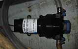
Jabsco Water Puppy (Model 18660-0121).
Specs:
| Body | Bronze |
| Impeller | Neoprene p/n 6303-0001, -0003 nitrite for oil-resistence |
| Voltage | 12 Vdc |
| Amp Draw | 8 amp |
| Fuse Size | 15 amp |
| Port Type | 1/2" Internal Pipe Threads |
| Dimensions | 3 x 4-3/4 x 6-3/8 inches (7.6 x 12.0 x 16.2 cms) |
| Weight | 4-1/2 lb (2 kg) |
More information can be found in the Jabsco Water Puppy Technical Data Sheet
This pump is mounted on the port side of the stern lazarette. A white, corregated plastic ("Bilge-flex"), 3/4" I.D. hose leads from the bilge to the pump. A white, corregated plastic, 5/8" I.D. hose leads from the pump to a through-hull port on the starboard side near the stern. Note that this is the same port used by the manual bilge pump.
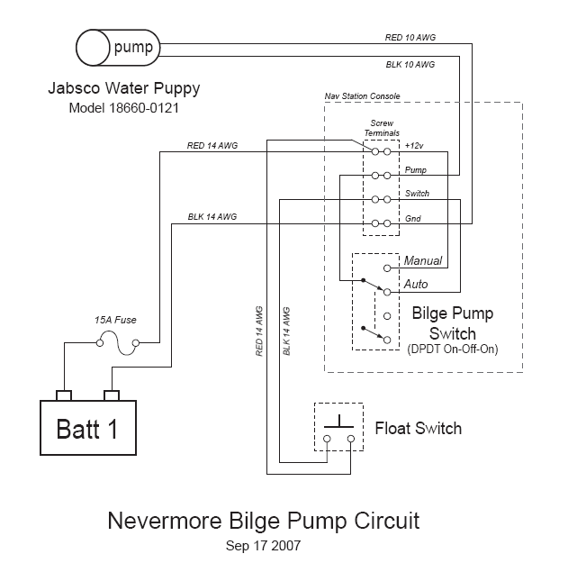
The bilge pump is wired directly from battery #1 to the 3-way switch on the nav station breaker panel. The up position manually turns on the pump. The down position puts the pump in automatic mode, in which a "float switch" will turn on the pump when water level in the bilge rises. A 15-amp fuse is inline with the positive lead from battery #1. The yellow rubber fuse holder for this fuse is strapped to the wiring harness that runs directly above battery #1.
Also see Bilge pump 3-way toggle switch table for an outline description of the above paragraph.
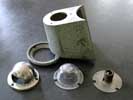
The float switch (which doesn't actualy float) for the bilge pump is located behind the aft-most panel above the port bench in the cabin (just forward of the nav station). An orange hockey-puck-sized rubber cover surrounds a microswitch which is affixed to a rubber diaphram. A black plastic air tube runs from the diaphram to a plastic air bell in the bilge. Rising water in the bilge will increase air pressure in the tube and activate the switch.
As of 9/3/2007, the switch is not sensitive enough to be activated by 6 inches of water.
Deeper water might activate the pump, but the required depth is unknown.
A newer model float switch (Jabsco Hydro Air Bilge Switch) will be ordered.
Old switch probably Licon Switch 11-330071 10-amp (per Thom scruffy note).
Manual Bilge Pump
This pump is mounted on stern lazaret to starboard of steering position. Its handle is tied to boat in stern lazaret. A second handle is aboard. Gray corrugated plastic hose, approx 1", leads from bilge to pump.
TODO: define hose to thru-hull, and position of thru-hull.
TODO: define model number, capacity, etc., of pump.
head
Nevermore is equipped with a standard marine toilet and a plastic holding tank. It is classified as a "Type III Marine Sanitation Device", which means that the waste is not treated, it is simply stored inside the holding tank until it can be pumped out. Note that there is no way to pump out the holding tank from the boat; the waste must be sucked out of the holding tank through the "waste" deck fitting.
The yellow handled seacock under the sink in the head allows seawater to be pumped into the toilet bowl. This seacock also serves as a scupper for the sink.
If the flush valve next to the hand pump is in the "flush" position (vertical), then seawater will be pumped into the bowl when the the hand pump is operated. If the flush valve is in the "pump dry" position (horizontal and to port), then no seawater will be added to the bowl during pumping.
The hand pump simulateously pumps seawater into the bowl (if the flush valve is open) and waste out of the bowl. The waste is pumped through about 15 feet of 2" O.D. hose, which includes an anti-siphon loop. After the loop, the waste goes into a plastic Y-valve with a blue handle that is under the sink basin. If you can read the words "to tank" on the blue handle, then the waste is being pumped into the holding tank under the port side V-berth. If you can read the word "overboard" on the blue handle, then waste is being routed to the large bronze seacock.
During normal operation of the vessel, the Y-valve should be in the "To Tank" position and the large bronze seacock should be closed.
Three hoses go from the holding tank up to the port side deck. A 2" diameter hose goes to the pumpout port on the deck (labeled "Waste"). A 1" diameter hose goes to a water inlet port next to the pumpout port. This inlet has garden hose threads and can be used to facilitate flushing out the holding tank. Another 1" diameter hose goes from the top of the holding tank to an air vent on the upper topsides, just below the pumpout port.
ice box
- The ice box is cooled by ice or by dc refrigerating system
- there are two levels in the cooler, separated by a wood lattice
- water from the ice box drains to the bilge
- the compressor is mounted in starboard lazarette
- the ice box is mentioned in the Owners Manual page 11
STATUS: as of 12apr09, do not use the compressor to cool the refrigerator. it draws some current but apparently does not do any cooling.
TODO: record model number of compressor
TODO: record volume of ice box
Stove
See T37 Owner's Instructions pages 16-17 for operation of the stove.
SAFETY COMMENTS:
Based on experiences on Aleida with the same kind of stove, a few items of these instructions should be highlighted.
- The statement that "the gas is burned in much the same manner as in a home has stove" is literally true, but somewhat misleading because it might imply that one turns on the gas, lights the stove, and is ready to cook. However, the steps 7, 8, 9, and part of 10 -- which comprise turning on the gas and lighting the stove, imply a more complicated situation, and with good reason.
- Especially step 7 -- wherein we get some alcohol into the lower part of the burner -- is important to get right. We can suggest looking in the burner with a flashlight as the valve is turned on to "watch the alcohol flowing into the little pan," to make SURE not to get too much fuel in the little cup. Maybe the "one turn" on is an excessive amount to turn the valve on, unless the stove hasn't been used for awhile. [At least one Aleida skipper found it IMPOSSIBLE to describe what's needed without a demonstration...]
- Part of the instructions in step 8 include "if the flames are licking at the overhead, ... extinguish with water." Think about it: if you're gonna boil some water anyway, why not draw it BEFORE your first times at lighting the stove.
- We note that step 11's order of turn-off (master shut-off valve first, then burner valve) may be different from instructions in the paperwork that came with the stove, and was not used on Aleida as far as I [ThomS] knows. However, it does give a more safe condition for the stove when it isn't being used, purging pressure from the fuel line.
Fresh Water System
Page 10 of the T37 Owner's manual describes operation and maintenance of the fresh water system; however, the system has been changed, especially concerning filling the tanks, as mentioned later below.
The fresh water system is supplied by 2 tanks, a 30-gallon tank on the port side, and a 60-gallon tank on the starboard side. Each tank has 2 inspection ports which are easily accessed through the lower berth/bench on either side of the main cabin.
Valves under the cabin floor connect the two tanks. Either tank can supply water to the ship's fresh-water system, or both tanks can be linked together.
There are two fill fittings on the starboard deck; the forward fill fitting fills the port tank, and the aft fitting fills the starboard tank.
The original configuration had only ONE fill fitting. Nevermore's copy of the Owner's manual has been marked up to indicate how to fill both tanks (the original configuration required filling the port tank through the starboard tank.)
Note the admonition (also on page 10, in the "HOT WATER" section) that the fresh-water pump should be ON while heating water using 110-volt shore power. The water is usually warmed by the engine's fresh-water cooling water; this does not require the pump to remain ON; there's no control to turn this heating on or off.
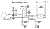
A rough sketch of the water system is being used (2007-08) to replace all the freshwater hoses; it indicates all associated devices and parts, and indicates their planned interconnection.
(this is a rough diagram - just testing my ability to upload images to the wiki)
Fresh Water Pump
Jabsco Par-Max 3.0 (Model 31395-3000).
Specs:
| Voltage | 12 Vdc |
| Amp Draw | 5.2 amp @ 10 PSI |
| Fuse Size | 10 amp |
| Flow | 3.0 GPM |
| Ports | "Snap-Fit" ports with 1/2" hose adapters |
| Dimensions | 9 x 4.2 x 4.75 inches |
| Weight | 4-1/2 lb (2 kg) |
The water pressure pump is located just forward of the starboard tank, under the lower berth. Diaphram design allows pump to run dry without damage. Internal pressure sensor stops the pump when working pressure is acheived.
Fresh Water Strainer
Jabsco Pumpgard (Model 36400-0000)
Water from one or both tanks is filtered by a steel screen strainer which is inline just before the water pump.
The strainer can be cleaned by unscrewing the plastic cover from the top, removing the cylindrical screen, and rinsing it out with fresh water.
Water Heater
Nevermore's water heater is a Raritan 1700, 12-gallon, 120V heater, Model #171211. This unit was purchased Spring 2008.
Specifications:
- Electrical Recovery Rate = 13 gallons (49.2 liters) per hour
- Maximum Operating Pressure:
- Tank: rated at 150 psi (1034kPa)
- With Temperature and Pressure Valve Installed: 50 psi (345kPa)
- Amps: 10 (120V AC)
- Required Circuit Breaker: 15 amps
- Thermostat: Adjustable; Factory Set to 120°F (49°C)
- Anode: Magnesium
Maintenance issues:
- Magnesium anode should be checked once per year
Ship's Electrical Subsystems
The 12-volt DC wiring circuits and the 110-volt AC circuits are functionally and electrically isolated from one another, except for the 12-volt battery charger which is powered by 110-volt AC shore power. DC-to-AC ground isolation must be performed within the charger.
The Tartan 37 wiring diagram provided in the Owner's Instructions can be used as a general guide to Nevermore wiring. However, this Oct 1976 drawing is different from the 1980 as-built configuration as we deduce it, as discussed in comments to the wiring diagram.
The as-received (2007) configuration of wiring will be discussed in sections for 12-V DC and the subsection battery charger, and in section 120-V AC below.
12-Volt DC
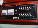
The switch panel above the nav table is organized into groups of controls including (from left to right):
- Meters for battery voltage and current
- Electric Bilge Pump Switch (switch #01)
- Main Switch Sub-Panel - two horizontal rows of 6 switches or switch/breaker combination
- top row has 6 switch/breaker devices (switches #11 - 16)
- bottom row (probably) has 6 switch-only devices (switches #21 - 26)
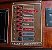
- Secondary Vertical Switch Sub-Panel - 7 switching devices a mix of switch-only and switch/breakers (switches #31 - 37)
- Nav Instruments Sub-Panel
- See nav_station_switches for tables of usages of individual switches.
- See nav_station_switches_wiring for diagrams and discussions.
Meters (volts and amps)
Meter ranges: voltmeter 0 - 25 VDC; ammeter 0 - 50 A
Voltmeter quirk: it appears to read high by approx 1.4 or 1.5 volts. The zero-point for the meter has been adjusted to read battery voltages correctly therefore the zero-point will be off-scale.
- Note: an expanded-range voltmeter might be better, e.g. 9 - 15 VDC.
Ammeter reads only the current being used by some of the ship's systems, but not any usage by the engine; it especially does not indicate battery charging; the ammeter on the engine control panel does that.
In addition, the ammeter terminal with 12-V feed from the batteries (red "thick" wire (approx #10-gauge) also has a "thick" white wire going back out of the panel via the wiring bundle; we suspect there's a ship's system which is powered by this wire which does NOT have its current reported by the ammeter.
TODO: trace the white "thick" wire from the ammeter and find the unknown ship's system.
Electric Bilge Pump Switch
- OFF, AUTOMATIC, or MANUAL operation of the single bilge pump.
- Voltage is ALWAYS on to this switch, even when main rotary switches are OFF.
- It is always connected to power from Battery #1, through an inline fuse located in the wiring harness above the battery. Removing the fuse removes voltage from the main panel's bilge-pump circuits.
- See Electric Bilge Pump
A note on terminology: The terms "bilge" and "sump" are synonymous on Nevermore; Tartan's original "sump" was a separate catch-basin for ice box and shower water, while "bilge" was used normally. As far as we know (Sep07), the "sump" isn't used any more, and we use the 3-way switch to provide
- TODO: mark up T37 Owner Manual page 11 to NOT talk about the "sump".
- TODO: check whether the refigerator (ice box) still drains water into any kind of sump.
Main Switch Sub-Panel (horizontal switches)
- Twelve combination switches/circuit-breakers arranged in two horizontal rows (switches #11-16 and 21-26).
- Battery voltage to this sub-panel's switches is OFF unless battery power is ON on one (or more) main rotary battery switch.
- No voltage is applied to the remainder of the 11 switches unless the upper-left-most switch of this sub-panel (named "MAIN") is on.
- See nav_station_switches for tables of usages of individual switches.
- See nav_station_switches_wiring for diagrams and discussions.
Vertical Switch Sub-Panel at Nav Station (switches #31-37)
Note that the horizontal sub-panel's "main" switch does NOT control power to this sub-panel; it is not separately fused.
- See nav_station_switches for tables of usages of individual switches.
- See nav_station_switches_wiring for diagrams and discussions.
Nav Instruments Sub-Panel
This control subpanel is completely disconnected.
Batteries
Batteries #1 and #2
- Batteries #1 & #2 controlled by top main rotary switch.
- They are "mixed use" (starting and deep discharge) batteries of the same type
- They are located below nav station seat: #2 is fwd, #1 aft
- Model: Powermaster DC-27P, flooded, 750 MCA, 200 min reserve
Battery #3
- Battery #3 is controlled by bottom main rotary switch.
- It is a "heavy duty marine starting" battery
- Located under the stairs, just forward of the engine.
- Model: Powermaster (unknown model), flooded, (unknown values)
Rotary Battery Switches
- The two rotary battery switches are Guest 2300A, 360-amp, 600-amp momentary.
- Both have AFD (alternator field disconnect) but they aren't wired, hence it is very important that at least ONE battery be selected ON at all times that the engine is running.
Emphasizing importance of above: we've found NO alternator protector (West Marine catalog index term) to prevent over-voltage from blowing the alternator's diodes when all batteries are turned "OFF" while running the engine; nor are the AFD (alternator field disconnect) contacts on the main switches wired (nor can they BE wired, with the present wiring of the bottom switch Batt #2 contact.)
- TODO: put some of the AFD unwirability discussion in a "quirk" section,
and make a simpler statement in THIS paragraph...
- See Main Batteries Usage Strategies for instruction and rationales for battery switching and use.
- See Main 12-volt Control Schematic Diagram which includes schematic (graphic) and a walk-thru of circuitry (text).
Tri-Color/Anchor/Strobe
- Model: Aquasignal Series 40: tricolor / anchor / strobe, quicfits (Model # 40806)
- "Quicfits" connector means that the unit can be easily unclipped from the top of the mast by sqeezing the black tabs at the bottom of the unit and pulling the whole assembly up.
- Bulbs:
- tricolor: 12V, 25W, 15D bayonet base (Aquasignal Part# 90002)
- anchor: 12V, 10W, 15D bayonet base (Aquasignal Part# 90005)
- strobe: 12/24V, 8W, Xenon Strobe (Aquasignal Part# unknown - maybe 90009)
- Visibility (from Aquasignal website):
- tricolor: 2nm
- anchor: 2nm
- strobe: 3nm
- Aquasignal Website
Steaming/Foredeck Light
Make and model is unknown. Similar models use 10W bulbs for steaming light and 20W flood bulbs for foredeck illuminaton.
- TODO: determine make and model
- TODO: determine bulb types
Sidelights/Sternlight
- TODO: determine bulb types (NOTE: red & green colored bulbs are required (no lenses are fitted))
120-V AC Battery Charger
Xantrex Truecharge 10TB Multistage Battery Charger.
This charger uses microprocessor-controlled three-stage charging:
- Bulk: Replaces 70-80% of the battery’s state of charge at the fastest possible rate.
- Absorption: Replenishes the remaining 20-30% of charge, bringing the battery to a full charge at a slow, safe rate.
- Float: Voltage is reduced and held constant in order to prevent damage and keep batteries at a full charge.
Specs:
| Output current | 10 A @ 14.5 V nominal |
| Output voltage (charge) | 14.2 - 14.4 VDC |
| Output voltage (float) | 13.5 - 13.8 VDC |
| Input voltage | 90-135 VAC, 50/60 Hz) |
| Number of battery banks | 2 |
| Configurable battery settings | Sealed (Gel & AGM) / Flooded |
| Recommended battery size | 25 Ah to 100 Ah |
| Dimensions (H x W x L) | 2.75 x 6.7 x 15.1 inches |
| Weight | 3 lb |
| AC Connector | 3-prong 15A household plug |
| DC Connectors | Two 2-pin molex connectors |
Documentation on this charger:
- File:Xantrex Truecharge10B OwnersManual.pdf
- File:Xantrex Truecharge10B DataSheet.pdf
- File:Xantrex Truecharge10B TechNote.pdf
Note: This charger is not yet installed. See the Upgrade 120v Electrical System task for more details.
The previous battery charger was Battery Charger Raritan R3012-3. It was removed from the boat in July, 2008.
120-volt AC
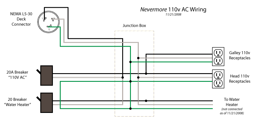
120-volt AC power is supplied to the ship via a standard male twist-lock shore power connector (NEMA type L5-30), mounted on the exterior of the port-side cockpit coaming by the stern.
- Note: The shore power is the aft-most of 2 connectors. The other connector was for "phone" and is completely disconnected.
Two switches/breakers are mounted on the aft side of the "Emergency" supplies cabinet next to the nav station. The Tartan documentation lists these as 20-amp breakers, although no amperage is designated on the actual breakers.
The left breaker is labeled "110 V AC" and supplies power to standard household AC receptacles (NEMA type 5-15). One pair of receptacles is above the galley sink, and another pair of receptacles on the aft side of the sink cabinet in the head.
The right breaker is labeled "WATER SYSTEM" and supplies power to the water heater. The power cable to the water heater is not connected (as of Nov 21 2008). The "110 V AC" breaker does not need to be switched on for the water heater to work. However, the Owner's Instructions pp. 10-11 demands that -- when the water heater 110V breaker is ON -- the freshwater pump must also be left ON.
All 120v cables terminate in a round plastic junction box located on the port side, just forward of the nav station, in a cabinet where life jackets are stowed.
- Note: The ground connectors of all receptacles and cables are all connected together but none are connected to the DC grounding/bonding system of the boat.
The Tartan 37 wiring diagram provided in the Owner's Instructions Section V presents the 120V-AC circuitry on Nevermore as MIT received her, except that the battery charger isn't shown. (Remember that the 12V-DC circuitry on this schematic can only be a general guide to some circuit configurations.) Note that this diagram explicitly states that "shore power is totally independent from ship's ground;" i.e., it is unlikely any galvanic isolator or isolation transformer was removed from the boat like one might think.
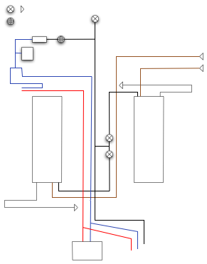
The diagram below shows the 120V-AC configuration after the battery charger that came with Nevermore was removed.
Miscellaneous notes:
- Two shore power cords are aboard, both with 30A (120-volt) locking connectors. Each is probably 25 foot length or more.
- Three or four short converter cables convert from male "marine" locking connector (on dock) to 3-pin "household" female; "household" male to "marine" female to the boat; don't remember the 2 others, probably e.g. 120-volt 50-amp locking male to 20/30-amp and/or 1 leg of 240-volt locking male to 20/30-amp locking female.
TODO:
- define and implement AC -vs- DC grounding circuit and circuit breakers to
- provide isolation of AC & DC grounds to preclude galvanic action on ships parts
- provide safety grounding and circuit-breakers to prevent crew electrocution or fires for a mis-wired AC feed
- check the config of the 2 short converter cords Thom can't remember what are (see above).
- measure length of the two long cords.
- define steps for polarity checking of the shore power source: for example, something like:
- first choose shore power adaptor to get to 30-amp shore-power receptacle (if required);
- use shore-power -to- flat-pin ("household") connector to then use ground-test lights unit to check the dock's configuration; (use boat end of shore-power cable if dock power is 30-amp connector)
- connect shore-power cable to boat;
- (can also) use ground-test lights unit in ship's flat-pin receptacles.
Anti-Electrolysis
See also discusssion of Electrolysis (AKA "galvanic corrosion" and "stray-current corrosion".)
Zinc Guppy
Cable should be clipped to backstay and threaded through ship's wheel.
Note that stern pulpit and lifelines are not grounded (2007).
Zincs in Engine
There are two pencil-zincs protecting the engine; one is in the heat exchanger, and one is in the oil cooler.
See Engine zincs replace 2007 for a report and discussion of replacing the two engine pencil-zincs.
See pp.220-221 Westerbeke Parts List, item 33, #11885
- pencil-zinc in heat exchanger item 23
- pencil-zinc in lube oil cooler item 32
Engine manual mentions something like "zinc in heat exchanger" (p.20) but doesn't mention one in oil cooler.
Zinc on Prop-Shaft
P1090819-zincs-2007-144p6q shows the prop-shaft zincs Fall 2007, printed large enough to show their inhabitants and erosion of the zinc a bit. Two new zincs were installed on prop shaft Spring 2008.
Anode in Water Heater
There is a magnesium anode in the water heater. [See water heater section.]
Note that this anode is in the engine fresh cooling water circuit; a zinc anode is NOT applicable. Anodes can be ordered from Raritan; the manual says anode part number is 1790010 for our 12-gallon tank.
TODO: Locate the anode on the unit and document it herein.
lightning-dissipation
Nevermore has NO specific lightning-dissipation .
Electronics
Fathometer
Model: Datamarine SL200DL
Serial No.: 012726
Depth Transducer:
- Model: Airmar B17 "Retractable Low Profile"
- Frequency: 200kHz
- Part No. (on cable tag): 31-241-3-01
- Purchased new: May 2008
Powered on by "NAV INST" circuit breaker on Nav Station Switch Panel 1. "MAIN" breaker switch must be on.
Tested on Aug 11, 2008. Depth sounder reads 25 feet in 28 feet of water.
Knotmeter
Model: Datamarine DCS100
This instrument is missing. It was last seen Fall 2007.
The speed transducer is in the posession of Ted Young.
The "dummy plug" core is in place in the boat.
Windmeter
Model: Datamarine LX360
Serial No.: 012128
GPS - Fixed Mount
Model: Garmin GPSMAP 276C
Software Revision: 5.20 (current as of Jun 9, 2008)
Specifications:
| Unit dimensions: WxHxD | 5.7" x 3.2" x 1.9" (14.5 x 8.1 x 4.8 cm) |
| Display size: WxH | 3.0" x 2.2" (7.6 x 5.6 cm) |
| Display resolution | 480 x 320 pixels |
| Display type | 256-color TFT |
| Weight | 13.6 oz (385 g) |
| Battery | rechargeable internal lithium-ion |
| Battery life | up to 15 hours |
| Waterproof | yes (IPX7) |
| Antenna | detachable 50-ohm BNC |
| NMEA input/output | NMEA 0183 |
| Basemap | yes |
| Built-in memory | none (cannot load maps to internal memory) |
| Accepts data cards | Garmin data cards |
| Waypoints | 3000 |
| Routes | 50 |
| Track log | 10,000 points |
Features:
- Garmin sonar compatible: yes
- Supports DSC (displays position data from DSC capable VHF radio): yes
- Audible alarms: yes
- Tide tables: yes
- Hunt/fish calendar: yes
- Sun and moon information: yes
- Automatic routing (turn by turn routing on roads): yes
- Headphone jack/audio line-out: yes
Garmin Chart Cards:
- Bluechart: Cape Cod: Model US003R (Jun 2007)
- Gloucester through New London, including Narragansett Bay, Block Island, Martha's Vineyard, Nantucket Island, the entire Cape, and includes general coverage Georges Bank
- Bluechart: South Maine: Model US002R (< 2006)
- Penobscot Bay through Gloucester, including Casco Bay and Cape Ann
Documentation:
GPS - Handheld
Manufacturer: Magellan
Location: drawer under nav station
RADAR
- Display: Ratheon R20XX display unit (mounted to the left of the nav station)
- Antenna: Raytheon R20XX raydome antenna (mounted on the mast)
Status (May 23, 2008) System has been tested "on the bench" and appears to function correctly. See full status report
RADAR detector
C.A.R.D. (Collision Avoidance Radar Detector)
- Manufacturer: Survival Safety Eng., Inc.
- Model No.: 060
- Serial No.: 9140470604
Detects radar signals from other boats and sounds alarm and indicates octant of bearing to the ship.
Not installed as of June 9, 2008
VHF Radio - Fixed Mount
Tranceiver:
Model unknown
Coax Cable:
- 16(19X29) stranded tinned-Cu center conductor
- Foam dielectric
- Type IIA white marine jacket
- Nominal Impedance 50 Ohm
- Velocity of propagation 78%
- Outer diameter .242"
- 98% tinned Cu braid.
- installed new cable in mast: May 2008
VHF Antenna:
- Manufacturer: Digital Antenna
- Model: 200 Series: 222-VW
- 3-foot stainless steel antenna mast
- Quick antenna mast disconnect
- Connector: UHF female (SO239)
- Impedance: 50 ohms
- Max Power: 100 watts
- 3dB gain
- VSWR: < 1.2:1 @ 156.8 MHz
- Ordered new: May 2008
VHF Radio - Hand-held
Model: Icom VHF Marine Tranceiver IC-M34
- Serial No.: 0115406
Features:
- Submersible (1m depth for 30 min.)
- Dual/Tri-watch functions
- Weather channel reception
- Auto Scan function
Specifications:
| Transmit Frequencies | 156.025 - 157.425 MHz |
| Receive Frequencies | 156.050 - 163.275 MHz |
| Usable channels | INT, USA, CAN, WX channels |
| Type of emission | 16K0G3E (FM) |
| Transmit Current (at 5W output) | 1.5A |
| Receive Current (at AF max.) | 200mA |
| Antenna Impedance | 50 ohms (SMA) |
| Dimensions (WxHxD) | 2-7/16" x 3-13/16" x 1-17/32" (62 x 97 x 39 mm) |
| Weight | 10.8oz (305g) |
| RF output power (Hi/Low) | 5W, 1W (2W w/ alkaline batteries) |
| Audio output power | 0.35 W |
- Charger: Icom Desktop Charger BC-173


