Difference between revisions of "Upgrade 120v Electrical System"
(→Recommendations: Added Costs) |
(→Status) |
||
| Line 2: | Line 2: | ||
== Status == | == Status == | ||
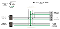
| − | [[Image:Nevermore_110ac.png|thumb=Nevermore_110ac_thumb.png|right|Nevermore 120v Electrical Diagram]] | + | [[Image:Nevermore_110ac.png|thumb=Nevermore_110ac_thumb.png|right|Existing Nevermore 120v Electrical Diagram |
| + | (Fall 2008)]] | ||
As of Nov 21 2008, the 30-amp shore power connector (NEMA type L5-30) on deck is connected to the onboard 120v receptacles through a switch/circuit-breaker mounted on the aft side of the emergency equipment cabinet. The Tartan documentation lists this switch as a 20-amp breaker. The hot water heater is not connected to AC power and the old batter charger has been removed. | As of Nov 21 2008, the 30-amp shore power connector (NEMA type L5-30) on deck is connected to the onboard 120v receptacles through a switch/circuit-breaker mounted on the aft side of the emergency equipment cabinet. The Tartan documentation lists this switch as a 20-amp breaker. The hot water heater is not connected to AC power and the old batter charger has been removed. | ||
Revision as of 12:16, 6 April 2009
A number of upgrades are recommended for the boat's 120v electrical system. It is intended that this task will be completed over Winter 2008/2009.
Contents
[hide]Status
As of Nov 21 2008, the 30-amp shore power connector (NEMA type L5-30) on deck is connected to the onboard 120v receptacles through a switch/circuit-breaker mounted on the aft side of the emergency equipment cabinet. The Tartan documentation lists this switch as a 20-amp breaker. The hot water heater is not connected to AC power and the old batter charger has been removed.
Issues
Some of the issues with the current 120v system include:
- No master double-pole breaker for 120v system.
- No galvanic isolation from shore power
- Existing breakers are old and of unknown reliability
- 120v receptacles are not GFCI
- Water heater is not connected
- Battery charger is not installed
- No status indication of ground fault or reverse polarity on shore power.
Recommendations
New Breaker Panel
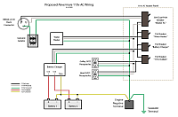
The existing breaker panel should be replaced. The new panel should include:
- A 30-amp double-pole switched master breaker that interrupts both "line" and "neutral" connections from shore power.
- Reverse-polarity indicators to indicate if "line" and "neutral" are interchanged on the incoming shore power voltage.
- At least three sub breakers that are fed from the 30-amp master breaker:
- 120v receptacles (15 amp)
- Hot water heater (15 amp)
- Battery charger (amperage requirement unknown)
- Lights and/or a meter to indicate if voltage is present.
The following would be an acceptable replacement panel: Paneltronics 9972313B 3-Position Panel
Galvanic Isolator
A galvanic isolator should be installed between the ground lug on the shore power connector and the boat's 120v ground system. This isolator should be located as closely as possible to the shore power inlet connector. It is proposed that the isolator be placed on the aft-side of the bulkhead underneath the port-side cockpit seat. This is directly underneath the cockpit instruments, and directly aft of the port-side berth.
It is recommended that the current rating of the isolator be at least 120% of the breaker rating of the shore power that is feeding the system. The following isolator is one of several that meets this requirement: Guest 50/60 Amp Galvanic Isolator
GFCI Outlets
Existing 120v AC receptacles above the galley sink and in the head should be replaced with GFCI outlets. If there is potential for water to be splashed on the outlet (such as the one in the head), the outlet should be equiped with hinged covers.
A third set of GFCI receptacles could also possibly be located near the nav station. This way, people can plug in laptops, or other personal gear, and use them at the nav table, without runnning a power cord across the companionway steps and over the sink.
AC/DC Ground Connection
A heavy (6 AWG) wire should be run from the 120v ground system, preferreably at the main breaker, directly to the engine "negative terminal".
Water Heater
The water heater needs to be connected to AC power and tested. Note that it should NOT be powered on, unless it is completely filled with water (wait until spring to test).
Junction Box
Junction boxes in marine 120v systems are not recommended. If possible, the junction box just forward of the nav station (in the PFD cabinet), should be eliminated and all 120v wiring should run directly to the new breaker panel.
Cost
| Galvanic Isolator | $189.99 |
| Master AC Panel | $151.99 |
| 2 GFCI Outlets | $24.00 |
| Wire | $30.00 |
| Total | $395.98 |

