Difference between revisions of "Engine 40 10 CBs panel access"
(ENGINE: Ckt Brkr location) |
(ENGINE: discussions of CBs & access) |
||
| Line 1: | Line 1: | ||
| + | [Navigate UP to [[Engine_schematic_dgm | Engine Schematic]]] | ||
| + | == Engine Circuit Breaker panel == | ||
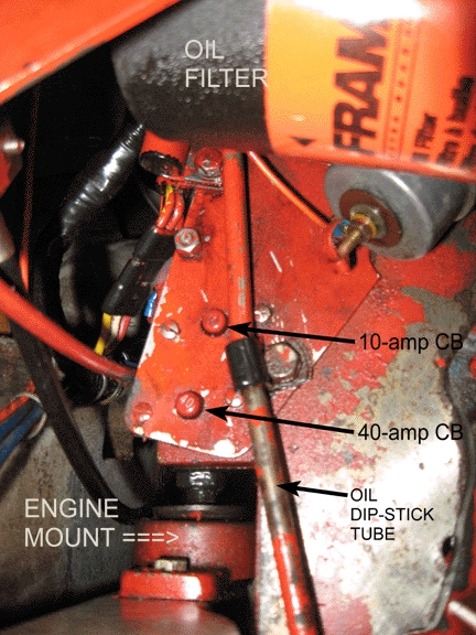
| + | The picture below indicates the location of the panel holding the 40-amp and 10-amp circuit breakers. | ||
| − | + | The 40-amp CB protects the 12-volt circuit for the pre-heating and the engine starter solenoid. Neither of these functions is operational if this CB is "blown". | |
| + | |||
| + | The 10-amp CB protects the engine instrument lights and their senders, and the audible overheat/low-oil-pressure alarm, in the circuit that gets activated when the engine is running and a sensor detects fuel pressure near the final pump. | ||
| + | |||
| + | We (ThomS/Oct10) haven't found any mechanical drawing in the parts list manual that shows location of these CBs. They ARE listed in the parts tabulation page 233 items 45 and 46 and are also shown in the wiring diagram. In addition, they have "See Note B" and "...C" respectively in the wiring diagram; however, this drawing doesn't have notes. However, the schematic diagram DOES have the notes, and the "B" and "C" indeed correspond with the wiring diagram's "see" notes. | ||
| + | |||
| + | We see a visible dip in voltage in the Nav Station voltmeters when the "pre-heat" button on the engine control panel is pressed and the CB is NOT "blown". There'll be an obvious dip in voltage when the "start" button is pressed, but since the engine also is being turned over, the dip from the starter motor swamps the dip of the solenoid. | ||
| Line 9: | Line 18: | ||
== Engine Circuit Breakers Access from Cabin == | == Engine Circuit Breakers Access from Cabin == | ||
| + | |||
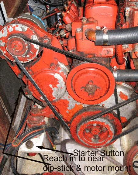
| + | The CBs are somewhat visible from the cabin when sighting in the lower "tunnel" on the starboard side of the engine. This gap between engine ganglia and the fire bulkhead allows access to the buttons. The "heads" of the two CB buttons wiggle slightly, as contrasted with the screws and nuts also on the mounting bracket. The oil dip-stick appears to be a good landmark, with its clamp near the CBs. The photo tries to point the way to "reach in to near dip-stick & motor mount" but the view given by this snap may not show the exact axis of our "tunnel" to reach into; the forward motormount is shown aft of the red button, and is on the same mounting bed as the "engine mount" indicated in the picture with the CBs. | ||
| + | |||
| + | Also in this "tunnel" are the termini for the throttle cable (more forward) and the engine-kill cable (more aft, but forward of the CB panel.). Both operate by killing or engine-killing when pulled forward. Thom's opinion is that there's no possibility of fouling the cables by pulling their attached levers forward, but that they should be pushed aft-ward (to allow running, or to speed engine) with delicacy, because of a perceived possibility of bending the inner cables. | ||
| + | |||
| + | TODO: verify that kill cable is aft, and throttle is forwardly located. | ||
| + | |||
| + | DANGER!! The inside enging-cranking button is pointed out; it's easy to lean into, turning the engine over. It operates even if the 40-amp CB is "blown"! And not indicated, but shown clearly, are the two belts and four (!) pulleys which are real crew-eaters!! And a minor area where we may injure the boat, but not ourselves, is the back of the top of the alternator, where the tachometer circuitry is exposed to mechanical mischief. | ||
| + | |||
| + | Also note that -- if the engine is cold enough to require pre-heating but the 40-amp CB can't be restored to "on" -- the red cranking button won't help because the pre-heat function depends on the CB providing voltage. | ||
| + | |||
[[IMAGE:Nmore-IMG_6729-CB_access_path.jpg | Access to 40/10-amp CB Panel]] | [[IMAGE:Nmore-IMG_6729-CB_access_path.jpg | Access to 40/10-amp CB Panel]] | ||
Latest revision as of 17:02, 29 October 2010
[Navigate UP to Engine Schematic]
Engine Circuit Breaker panel
The picture below indicates the location of the panel holding the 40-amp and 10-amp circuit breakers.
The 40-amp CB protects the 12-volt circuit for the pre-heating and the engine starter solenoid. Neither of these functions is operational if this CB is "blown".
The 10-amp CB protects the engine instrument lights and their senders, and the audible overheat/low-oil-pressure alarm, in the circuit that gets activated when the engine is running and a sensor detects fuel pressure near the final pump.
We (ThomS/Oct10) haven't found any mechanical drawing in the parts list manual that shows location of these CBs. They ARE listed in the parts tabulation page 233 items 45 and 46 and are also shown in the wiring diagram. In addition, they have "See Note B" and "...C" respectively in the wiring diagram; however, this drawing doesn't have notes. However, the schematic diagram DOES have the notes, and the "B" and "C" indeed correspond with the wiring diagram's "see" notes.
We see a visible dip in voltage in the Nav Station voltmeters when the "pre-heat" button on the engine control panel is pressed and the CB is NOT "blown". There'll be an obvious dip in voltage when the "start" button is pressed, but since the engine also is being turned over, the dip from the starter motor swamps the dip of the solenoid.
Engine Circuit Breakers Access from Cabin
The CBs are somewhat visible from the cabin when sighting in the lower "tunnel" on the starboard side of the engine. This gap between engine ganglia and the fire bulkhead allows access to the buttons. The "heads" of the two CB buttons wiggle slightly, as contrasted with the screws and nuts also on the mounting bracket. The oil dip-stick appears to be a good landmark, with its clamp near the CBs. The photo tries to point the way to "reach in to near dip-stick & motor mount" but the view given by this snap may not show the exact axis of our "tunnel" to reach into; the forward motormount is shown aft of the red button, and is on the same mounting bed as the "engine mount" indicated in the picture with the CBs.
Also in this "tunnel" are the termini for the throttle cable (more forward) and the engine-kill cable (more aft, but forward of the CB panel.). Both operate by killing or engine-killing when pulled forward. Thom's opinion is that there's no possibility of fouling the cables by pulling their attached levers forward, but that they should be pushed aft-ward (to allow running, or to speed engine) with delicacy, because of a perceived possibility of bending the inner cables.
TODO: verify that kill cable is aft, and throttle is forwardly located.
DANGER!! The inside enging-cranking button is pointed out; it's easy to lean into, turning the engine over. It operates even if the 40-amp CB is "blown"! And not indicated, but shown clearly, are the two belts and four (!) pulleys which are real crew-eaters!! And a minor area where we may injure the boat, but not ourselves, is the back of the top of the alternator, where the tachometer circuitry is exposed to mechanical mischief.
Also note that -- if the engine is cold enough to require pre-heating but the 40-amp CB can't be restored to "on" -- the red cranking button won't help because the pre-heat function depends on the CB providing voltage.

