Difference between revisions of "Nav station switches wiring"
(doc-struct & diagram only) |
m (walkthru - in progress) |
||
| Line 6: | Line 6: | ||
<hr> | <hr> | ||
| − | + | <br> | |
'''12-volt DC "hot" side of switches/circuit-breakers''' | '''12-volt DC "hot" side of switches/circuit-breakers''' | ||
[[IMAGE:IMG_0896-panel_power-7x6-96p.jpg]] | [[IMAGE:IMG_0896-panel_power-7x6-96p.jpg]] | ||
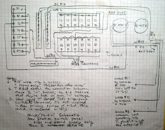
| + | ::(above) Diagram of wiring bringing 12-volt "hot" to switches and circuit breakers | ||
| + | <br> | ||
| + | The wiring above, bringing 12-volts to the switches so that -- when those switches are turned ON -- positive 12-volts will be available at the switches' terminals for which wiring is NOT shown on this diagram. | ||
| + | |||
| + | The wiring configuration is for the most part quite straightforeward, except for a couple things that we were not expecting when we started studying the wiring. | ||
| + | |||
| + | WALKTRHU: | ||
Revision as of 16:13, 10 February 2008
Description of 12-volt wiring in the Main Switch Panel is divided into two parts:
First, the wiring which brings 12-volt power to the "hot" sides of the switches and circuit breakers is shown.
Second, we plan to describe the wiring from the switched-12volt side of switches/CBs. It isn't clear to this writer exactly where we'll break these discussions out into the individual subsystems being controlled.
12-volt DC "hot" side of switches/circuit-breakers

- (above) Diagram of wiring bringing 12-volt "hot" to switches and circuit breakers
The wiring above, bringing 12-volts to the switches so that -- when those switches are turned ON -- positive 12-volts will be available at the switches' terminals for which wiring is NOT shown on this diagram.
The wiring configuration is for the most part quite straightforeward, except for a couple things that we were not expecting when we started studying the wiring.
WALKTRHU: